Category Archives: Layout Design

Layout Design, and Designs

Operations on a Maintenance Centre Layout (Part 1 – Facility Types)

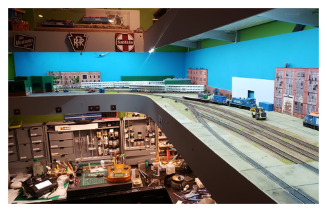
This is the first of a three-part series of posts on maintenance centre layouts, that started with Aaron Riley’s Metra service centre layout.  In this post, I’m focusing on helping you understand the types of prototype passenger facilities (or depots in Australian parlance) with which I’m familiar. Providing an overview of their services and facilities and where and how they fit into the passenger rail network.


Understanding what we’re modelling

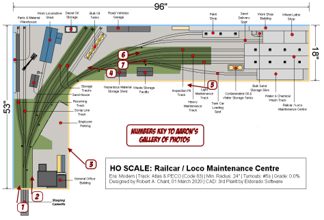
After looking at Aaron’s interpretation of Rob’s design I noticed a lot of variances from what I see at work each day. In this post I’ll show how you can adapt Rob’s design to better fit your needs, if like Aaron, you are focusing on passenger rail maintenance centres in a small space. Aaron’s layout focuses on modelling a mix of running and maintenance facilities rather than the heavy maintenance facility indicated in Rob’s original design. This is because he is modelling a location that has complete train sets waiting for use, as well as the minor maintenance facilities

By modelling the less specialised running depot, rather than the tightly focused Super or Heavy Maintenance centre opportunities for operation are available which might be missed by focusing solely on the upstream maintenance facilities.

Understanding these opportunities for operations on your given choice of layout come from understanding the scope of work that is able to be carried on a maintenance site, and therefore when a transfer (off layout) is required to a heavier maintenance facility. This understanding assists in the operating design and will add to the long term enjoyment of the model. Without losing sight of the fact that this is a small layout design, let’s focus on making the most of the space within the footprint of Rob’s original design by looking at the three types of passenger rail facilities with which I’m familiar and how each affects the size and operations possibilities of a layout.

There are other types of specific maintenance facilities (beyond the scope of this article) which we’ll look at later in the series. These I classify as rebuilders, scrappers, and leasers (think Larry’s Truck and Electric of McDonald, OH), that are large sites, usually in old railroad shops and simply too large for the small layouts I prefer to own, operate and design. In this vein, however, there are some smaller outfits such as McHugh Locomotive and Equipment that specialise in niche locomotive services for industrial, short-line and regional railroads as well as heritage, historical and vintage. I’ll link all of those in the resources section below.

Depot types

There are three types of passenger rail depot with which I’m familiar:

  • Running depots,
  • Maintenance (a.k.a. super) depots, and
  • Heavy maintenance depots.

Each type of depot fulfils a different role for the rail network. Primarily they allow the most efficient use of operational, technical, mechanical and overhaul capacity to keep trains running, and people moving and paying.. You as a modeller should keep in mind that the prototype site may contain more than one type of depot. So for example a super or heavy maintenance depot may also have attached to them a running depot. These can be modelled together (if you have the space), or individually depending upon the space available to your layout. We’ll look at the different depot types and what in general they contain; before we do we should understand that while each type of depot has unique functions and infrastructure, they also have things in common such as:

  • Staff amenities for train crew, maintenance staff, cleaners,
  • Administration/Office buildings
  • Sanding infrastructure and storage,
  • Cleaning infrastructure for external cleaning (a carriage/loco wash), and
  • Cleaning staff for internal carriage and locomotive cleaning which includes buggies to get around the site, cleaning carts, sanding vehicles to top-off sand for individual passenger cars, grey and black water drainage facilities, and so on.

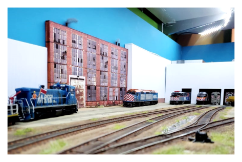
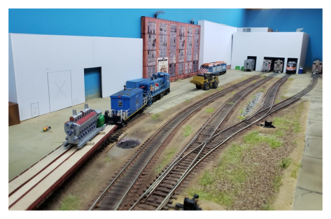
Within a footprint similar to Rob Chant’s original layout design for a passenger rail operation you are not going to be able to fit anything other than a running depot. And really with my preferences, I’d prefer to see a large range of train sets on the layout moving about. Having said all of that, let’s look at the different types of rail depots that I am familiar with.

Running Depots

Running Depots focus on getting units out the gate and onto the network. As such they have a small maintenance staff, performing minor fixes and repairs that assist in keeping units on the road. The maintenance staff also cover off periodic running inspections. For higher/major level maintenance and repairs, whole trains or individual cars are transferred to higher-level maintenance centres for action.

Maintenance (Super) Depots

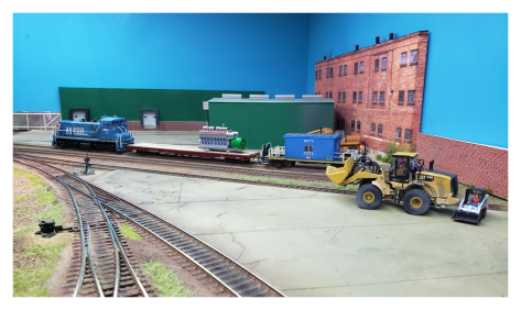
Maintenance (Super) Depots are the next step up and provide a means to perform heavier programmed maintenance of units. They will also perform minor accident, and easily performed system repairs and part swaps. It should be noted that you’ll often see contractor vehicles onsite at these locations (especially in the modern context to service HVAC, and other managed systems on units. One thing that I’ve not seen in facilities of this type are overhead cranes. These tend to be found only at the heavy maintenance centres. Super depots simply aren’t focused on these heavy industrial repairs, so there is no point in spending money when it is not required.

The facilities at these depots, above and beyond those available at the Running Depot are in general:

  • Wheel lathes,
  • Bogie drop/swap-out facilities,
  • Major component swap out (HVAC, etc.),
  • Under-floor mechanical servicing and repair
  • Engine/traction motor repairs
  • Driver’s cab/passenger saloon furniture repair/swap facilities (seats, toilets, instrumentation, electronic components, and sub-system components and storage for the same)

Heavy Maintenance Depots

Heavy Maintenance facilities are, as the name suggests, where major overhauls are carried out. In general, this would include late-stage programmed maintenance requiring engine/traction motor swaps and rebuilds, bogie exchanges and rebuilds, car body rebuilds, and so on. The facilities at these depots above and beyond those available at both the Running Depot and the Maintenance (Super) Depot are in general:

  • Rebuild facilities for all subsystems (electrical, traction, car body, subframe, collision repair, etc.)
  • Commissioning facilities (for new units being brought into service)
  • Decommissioning facilities (for units being removed from service), including storage for salvaged components waiting to be reused

Other types of repair facilities

There are other kinds of repair facilities. Generally, these fall into the following categories:

  • Manufacturers: where cars and locomotives under a contract arrangement go for major overhauls, collision and other damage repairs, and end of economic life extension work and upgrades
  • Junkyard traders: Think Larry’s Truck and Electrics who buy bulk locomotive lots from the class 1 railroads before:
    1. stripping saleable parts from life-expired units for on-sale to refurbishment companies, re-use in refurbishing their own lease fleet, or direct part resale to their own customers
    2. cutting up what’s left of stripped units for scrap for resale to scrap buyers for (hopefully) a profit
    3. refurbishing working locomotives in good condition for lease or sale to regional and shortline customers, and
  • Specialty rebuilders: think McHugh Locomotive who deal primarily with industrial, and smaller shortline and regional customers, offering a full range of locomotive servicing, repair and rebuilding options (interestingly their plant has no direct rail connection, although they do have a long history of moving locomotives using large tractor-trailer rigs and a cool website and youtube channel, so there’s that too)

Specialty rebuilders are a topic all their own. And I promise to come back to this specific


What’s in the next post?

In the next post, I’ll be focusing on developing an operating plan to suit a layout running depot style layout. This involves working through how the prototype does its operations and the methods they use to get train sets out of the yard and onto the main for timetable services. But I’ll share more with you in that post.


Resources

Staying in Contact

Interested in keeping in touch or discussing posts, pages and ideas?  You can do that in several ways:

Aaron Riley’s Metra Service Centre Layout

This post is made possible by Aaron Riley. I’d like to thank him for his assistance, his time and especially for supplying the images of his Metra maintenance facility layout that I first saw on Facebook (more information in the resources section at the bottom of the post). Adapted from a Robert Chant design in HO scale, Aaron has executed an exquisite small layout that in the photos does not look small. Let’s take a look around his Metra Service Centre.


Rob Chant’s layout concept

In the original Facebook post Rob Chant commented that while he “hadn’t designed [a maintenance facility style layout] before, he thought it would be something that would extend his model railway design skills“.

He said further that he thought “the layout owner’s space would be a good fit with his design and could include a load of detail and some support structures.”

I heartily agree with both perspectives. Rob’s concept and the layout Aaron built from it are outstandingly good and show what can be achieved in a small space. And remember, as you can see from the plan below it is not a lot of space; the layout is only 8′ (2400mm) in total length; with a total width of 4′ 5″ (1346mm) and maximum board width of 18″ (450mm).

Rob Chant's original Track Plan with numbers keying to Aaron's gallery of photos
Rob Chant’s original Track Plan with numbers keying to Aaron’s gallery of photos

And there’s a lot packed into that small space. Yet it doesn’t look crowded; quite the reverse is true. It looks wide, open and has relaxed look about it. Lived in, even.

Enough of the overview let’s dive in.


Looking around Aaron’s Metra layout

Image 1: Looking into the layout from the fiddle yard

In image 1 above, you can see Rob’s use of the administration building as a view blocker ensures that the viewer’s eye is distracted where the layout ends, and the staging begins. It’s a great design feature. In addition, provides a verticality to what would otherwise be a flat, horizontal layout. it gives the viewer, no matter the angle of viewing, a framed view of the layout. It’s a thoughtful design feature that makes Aaron’s layout, and Rob’s plan a cut above.

Image 2: Looking over the administration building toward the storage and engine tracks

In image 2 above, it is interesting to note Aaron’s prototype solution to the problem of overcrowding and short sidings. You’ll note the three-car set is fouling the two cars in the siding. This is common where older facilities were designed for shorter cars. Things get put wherever they’ll fit. During late nights most running facilities like this one are crowded, with train sets packed in like sardines. It’s nice to see that modelled, even if Aaron did so unintentionally. It really adds to the believability of the scene.

Image 3: View from the administration building - note the details in Aaron's scenes
Image 3: View from the administration building – note the details in Aaron’s scenes

In image 3 above, what I noticed first was the sense of openness. Taken from the other side of the Administration buildings, it is great that Aaron has been able to achieve this and fool the eye and the mind on what is a small footprint layout. And there is a wealth of detail too. I love the cracked hard standing area, not overtly achieved. Subtle but unmistakable. It is really great work and carried across the layout.

Image 4: A Metra transfer run prepares to leave for the heavy maintenance centre with a tired motive power unit

In image 4 above, what took my eye straight away was the photo-realistic building flat. It is an eye-catching feature. The prime mover looks to have just been loaded, as the tie-downs have yet to be fastened to the flatcar.  This transfer freight movement will be heading off to the upstream maintenance centre later where that prime mover will get a rebuild before being replaced into another locomotive. I’m impressed by how the scene has been dressed. With most of the buildings flat against the rear of the layout, wide-open space reigns. Cleverly done Aaron.

Image 5: With the maintenance centre behind you, it's amazing what you can fit in only 8 feet x 1.5 feet
Image 5: With the maintenance centre behind you, it’s amazing what you can fit in only 8 feet x 1.5 feet

In image 5 above, we’re standing roughly in alignment with the face of the maintenance centre buildings. No matter how many times I look at the scene, I just don’t see how it is not 16 feet long.

Image 6: Aaron's use of photorealistic buildings and large buildings add to the scale and apparent size of the layout
Image 6: Aaron’s use of photorealistic buildings and large buildings add to the scale and apparent size of the layout

In image 6 above we’re looking toward the heart of the maintenance centre. Cleverly Aaron has not tried to model the entire building, yet there is enough darkness to hide the fact that the buildings are not as deep as they appear to be. Once again, the height of the surrounding buildings, and the service centre, illustrate how even in a small space you can use the vertical to make things appear bigger than they really are. It is something I’ll be using on my current small switching layout when I get around to making the warehousing and other structures. Also, we see another of the photo-realistic buildings; with knocked out windows, rusty roller doors, and a run-down look from an earlier time. It grounds the newer parts of the layout and suggests a history we just haven’t heard yet.

Image 7: Aaron's use of tall photo-realistic and large new structures add to the vertical scale and complement the small footprint of the layout
Image 7: Aaron’s use of tall photo-realistic and large new structures add to the vertical scale and complement the small footprint of the layout

In image 7 above, you’ll note the uncluttered nature of the layout. There’s work going on here, but there’s room to get about, without bumping into things. This particular scene also shows the actual depth of the maintenance centre buildings, just a car length long. Not that you’d notice while switching. The layout ticks so many boxes for me in regard to how small layouts should be built. With thought and care not only in the design but also in the execution of that design.

I guess by now there’s no hiding it: I’m a fan of this layout. There is so much to learn from how Rob has designed and Aaron has built the layout. And there is much more that you can add to what’s already here. That’s for another post and another day, however!


What’s in the next post?

In the next post, I’ll show I’ll share my knowledge of the types of depots that passenger trains operate from in my experience.  It’s not something that is often discussed in the hobby press, or online groups. So if you have no idea what I mean by a running depot, we’ll cover that in the next post, and in the series of posts that follow.

Till next time; Andrew


Resources

  • Aaron’s original post on the Micro/Small Model RR Layouts group on Facebook – membership of the group required to access the post (and well worth it too!)

Staying in Contact

Interested in keeping in touch or discussing posts, pages and ideas?  You can do that in several ways:

Thoughts on modelling the Montpelier, OH Elevator

Small layouts have to meet the needs, and desires, of their owners. Often that is not easy as we want it all, but in a small space.  In this post, we’ll look at how you can work with the track layout from the elevator at Montpellier, OH (see this post) to fit in a smaller space, even if you don’t want to model an elevator.

There is so much that you can do with a good track layout!

Disclaimer

So before I begin, I wanted to make this clear:

  • If you want to model the Eden Co-Op, in an as-is, where-is format, if in a somewhat smaller version, knock yourself out. I’ll go through that in the section below.
  • However, should you want to use the track plan and model something else, then I have a few ideas about that for you too.

Now, feel free to read on.

Site overview

Image 1: The Eden Farmers C-Op Ass’n in Montpelier, Ohio USA

After clicking the image above, which I hope you’ll find interesting, you’ll note that the track arrangement is basically a double-ended Inglenook (I call it a Supernook) providing:

  1. a run-around option for the locomotive,
  2. off-spot locations for cars not being spotted under the over-track auger(s), and
  3. somewhere to go off the layout at the end of the session.
The track plan
Image 2: The track plan

And that neighbours, is everything we need to make an operating layout (see my Ops 101 series starting here for more).

According to our friend Google, the branch line is just under a kilometre at 941 metres (or 3084 feet) from the toe of the switch on the left of the branch to the road on the right. To model it all you’d need 35 feet and four inches, give or take. We’re into small layouts so we’re not going to do that.

Site Operation

The elevator receives empty blocks of cars inbound, shipping loaded blocks of cars out. The elevator has its own switcher (an SW-1200 of 1955 vintage) to do all the in-plant moves.  From the video I pointed to in the previous post, I’m guessing that there might be multiple types of grain available for loading within the block, and this is why the centre track is used to store cars before they are loaded.  You’ll note in the video that the switcher is pulling trucks from the centre track.

Assuming that there are no cars waiting to be loaded, the general operation goes something like this:

  1. Class 1 railroad switches a block of empty cars for loading by the elevator (pushing cars in from the yard – left of the above image). They place these cars onto the branch line (top of the picture)
  2. The plant switcher fires up, after being shore powered (it looks like they have a mains plug to float the battery voltage at the right-most building) overnight
  3. The switcher then hooks up to the first block of the inbound cars, pulls forward to the switching lead, and pushes the cars back onto the loading track (bottom track on the image above)
  4. Where a car is not in the right loading order, the switcher sets this car out to the middle track
  5. The switcher then repeats step 3, and step 4, as necessary until the cars are all loaded
  6. Once switching is complete the switcher then goes back onto the switching lead, is powered down and then reattached to shore power.
  7. The class 1 railroad now switches out the loaded hoppers and the cycle starts again.

Modelling Opportunities

As-Is

Modelling a single industry provides you with focus. In this case, it is a single commodity and car type operation. On the positive side though you only need to buy one locomotive. And there is lots of switching. And if that’s your thing then you’re good to go.

While the original site is really big, a model of it doesn’t have to be. You can build a layout based on this industry, using the simple principles of the Inglenook and model it in a lot less space by determining the maximum number of cars that you want to switch in any given session. And

Freelancing Opportunities

The elevator at Montpellier as shown in the last post is big; really, really big. It handles unit grain trains with an empties in/loads out procedure. So I guess you’re wondering “what is Andrew thinking!

A smaller version elevator

But we don’t want to model this site full size. Instead, we want to model a smaller version of the site. And for that, we’re going to use the classic Inglenook design that is double-ended so you can run around the cuts at either end (see this page for an overview of the Inglenook) to shorten the length to something more manageable.

From the track plan above you’ll note that I’ve named the tracks as Branch Line, Overflow and Elevator track. The branch line is the longest track, with the other two being roughly the same size. That is why the Inglenook is the perfect solution to shrinking the track down to a manageable size. In the resources section below I’ve listed the very best calculators (some on this site, others off) to help you determine the length and number of cars you can fit in a given space.

Same track arrangement, different industry

I can think of several industries that you could model, that require constant switching, mainly in the food industry (refrigerator cars, and boxcars primarily) that will keep your single loco crew hopping for each session. By keeping the same track arrangement cars would be left on the overflow track by the Shortline or Class 1 railroad, and then taken by the company switcher and placed onto the loading track.

To boost operations you could work as follows:

  1. The session starts with the loco on the right end tail track
  2. Empty cars are pulled from the overflow track and pushed onto the loading dock or to the loading doors
  3. As cars are loaded they are pushed to the end of the loading track
  4. More cars are pulled from the overflow track, and the cycle continues
  5. As space is freed up on the overflow track those loaded cars can be switched back to the overflow track using the branch line as the run-around
  6. Rinse and repeat until your loads are completed and a train of loads is assembled on the overflow track
  7. The session ends when the loco is parked up on the right end tail track

Here are my thoughts on what your food-based industries could be:

A frozen foods manufacturer (meat, vegetables, fish, you name it) – empties in, loads out with a slab-sided warehouse and environmental dock door arrangement.  A modern facility (from the 1980s onward) would be a better option. The doors would need to line up with boxcars of the era. Mostly 50 or 60 footer mechanical refrigerators. Luckily, there are plenty of those on the market at the moment.

Other industries off the top of my head are a breakfast cereal factory, or Snack cake bakery (think Hostess), plywood factory, auto part (castings) manufacturer, a food-service warehouse (a mix of dry and frozen doors would work here similar to the old Austin, TX SYSCO/US Foodservice warehouse, using doors rather than docks.

The list of ideas is almost limitless. If they ship a lot of stuff to other factories you could use the track plan and scale it down as needed for your site. Making it a stand-alone layout means you could have a small, high-quality operations based layout up and running quickly, and prototypically in just a couple of weekends. Then spend a couple of years adding detail you go. 1 locomotive, especially an older SW, rusty GP9 or a patched GP20 would do. Try a leased unit.

I hope this has given you an idea or two, and that you’ve found the post useful. In the meantime don’t forget to check out the resources below. Like, comment and subscribe if you find my content useful. I hope to hear from you soon.

Resources

Staying in Contact

Interested in keeping in touch or discussing posts, pages and ideas?  You can do that in several ways:

An Australian RIP (switching) layout

At the Corio Model Railway show in 2017, I was lucky enough to catch this outstanding Australian switching layout. Owned by Ian Wilson of Ian Wilson Models (which is sadly no longer in business) this layout was simply outstanding. You’ll notice that the layout is completely self-contained, with no off layout cassettes or fiddle-yard.

Despite that, it had all the needs for a working layout including a run-around to allow the single locomotive to serve all facing and trailing sidings.

At 2400mm (8′) long by 600mm (2′) wide, it was a delight to see operate in the flesh. Sadly I was advised today, that the layout is (sigh), no more.

If you have any images of the layout or further information on it, I’d love to know. Please contact me through this site’s contact page (which send me an email), or on the Facebook page with details.

Enjoy the gallery of images.


Resources

  • None in this post

Staying in Contact

Interested in keeping in touch or discussing posts, pages and ideas?  You can do that in several ways:

I’m working on a new series of posts – here’s a quick teaser…

It’s been a while right?

Shift work, long days, cold nights, and all that stuff.

The good news is there’s a batch of content coming focusing on Locomotive, and Railcar maintenance facilities… you are going to love it. How to model each one, operations possibilities and all in a small space. I want to thank Rob Chant and Aaron Riley for beginning the discussion on Facebook.

Here’s a taste of what’s coming over the next few days! The day it posts depends on how I feel after my second COVID-19 vaccination tomorrow. Here’s hoping for the best outcome and no headache, etc.

There’ll be more posts to come during October though covering a range of topics from the micro size to the mammoth 8′ x 2′ footprint, including:

  • Motive Power Depots (MPDs) for diesel or electric locomotives,
  • Electric Multiple Units (EMUs), and
  • Diesel Multiple Units (DMUs) throughout October.

Aaron Riley’s Metra Railcar Facility layout

Based on a Rob Chant design (more on that in the next post) Aaron has built a cracker ‘L’ shaped layout in only  96″ x 53″ with a width of only 18″.

This is a taster, there’ll be more in my next post!


Resources

  • Visit Rob Chant’s Facebook page for more great designs.

Staying in Contact

Interested in keeping in touch or discussing posts, pages and ideas?  You can do that in several ways:

Evans Hollow layout hits a milestone (been a long time coming)

The Evans Industrial shelfie layout has hit a major milestone! Read on…


A quick heads-up for those of you following along with the slow build of this layout. We’ve hit a major milestone, with the completion of the wiring of the layout underside. No track down at this stage, but that is coming in the next day or so, and aiming to be at the testing stage during the Mothers Day weekend.

(That’s the second week in May if you need reminding like me!)

I’ve completed the wiring to my wiring standards. You can download a copy from this site, just head down to the resources section at the bottom of the page.

Just a couple of notes for those of you wondering:

  • Yes, I love wiring and electrics
  • Yes, the wiring is designed as a modular unit, to facilitate troubleshooting and replacement as necessary over the years
  • Yes, the wiring is extensible, in that this layout will be able to join up with other small layouts  being planned in the future for this series
  • Yes, I had a lot of fun, and a little frustration – more on that in the article that I’ll be publishing in the next week or so – plus there’ll be a video too that I’m working on for the remainder of my vacation – I go back to work Sunday.

Hope that you have been able to get out and also do some modelling, and thanks for continuing to follow along with me. Stay well, stay safe, and stay modelling.

Regards Andrew


Resources

Staying in Contact

Interested in keeping in touch or discussing posts, pages and ideas?  You can do that in several ways:

Site Update – 26/03/2021

There’s a new section (Layout Design Basics) under the Articles menu. The first article there focuses on Inglenooks.


Layout design basics

I’ve added a new section on layout design basics under the ‘Articles’ menu. In the first page I’ve looked at the Inglenook. Bought about by the recent posts on the Montpelier, OH grain facility. Which is a double-ended Inglenook.

Inglenooks are a fascinating subject of study on there own, and really handy to come to terms with as a small layout designer since they can be used as a game, or in normal operating usage when switching your layout. All with the change of the number of cars on the layout.

There’s a lot of information on the page, and I’ve added links to the ultimate source of Inglenook knowledge too. Head on over to the page and check it out when you get a moment.


Resources

Staying in Contact

Interested in keeping in touch or discussing posts, pages and ideas?  You can do that in several ways:

More first Mile/Last Mile? We can do that…

I posted a while ago about a flour mill, here in Melbourne, that showcases a loads-in, empties out flour milling operation. Today we’ll look at another operation, this time in Montpelier Ohio which is an empties-in/loads-out facility for grain. This is truly first/last-mile railroading at its best.

Switching the Montpelier Ohio Elevator

We’ll talk about modelling a facility using the track layout and operations featured in this post next time. For now, I’d suggest that you watch this outstanding video from YouTuber Scott Taipale. With WAER 223 an SW 1200 switcher (ex IHRC 223, ex TRRA 1223) working a unit grain train at the elevator in Montpelier Ohio.

This SW 1200 switcher was built for the Terminal RR of St Louis in 1955. Later owned by the Indiana Hi-Rail and successor Wabash Erie, it is now used exclusively by the Edon Farmers Co-Op to handle the bulk car movements you’ll note in the video.

A couple of notes on the video from Scott:

  • The line furthest right (North) used to be Wabash’s 1st district which ran from Toledo to Montpelier (now truncated, it ends 4800 feet behind/east of the camera)
  • The branch line connects to the former Wabash yard in Montpelier (now Norfolk Southern)

In my next post, we’ll look at how you can model a layout based on the track diagram and how you can fit this facility into your space and time limitations. Thanks for reading along.  and if you get the chance please like and subscribe to this blog, and to the Facebook page. Your support is greatly appreciated.

Resources

My switching first/last-mile playlist on YouTube

Previous Kensington Posts:

Scott Taipale

Staying in Contact

Interested in keeping in touch or discussing posts, pages and ideas?  You can do that in several ways:

First mile, last mile railroading – what is it?

So what is it?

First-mile/last-mile railroading, what modellers refer to as customer switching, is the customer end of railroading. That is the setting out and picking up cars from a customer’s premises on the railroad. This can be directly from a customer’s spur, a ramp at the local yard or a team track, off the local mainline.

It is the point at which the customer and the railroad meet. All railroad economics relies on it and always has.  While in the modern era the customer has gotten bigger to take advantage of intermodel and block trains, the underlying forces remain the same. Customer shipping goods. Railroads picking up goods and moving them to their destination. Destination (consignee) receiving and accepting goods.

So why is this important to me?

For you, the small layout builder/operator, the first-mile/last-mile end of the operation is the:

  • simplest to model,
  • easiest to operate, and
  • most interesting to work with for the longer term

Whether you use a ‘tuning fork’, inglenook, supernook, or another layout design element you enjoy, by focusing on the customer end of the operation you make the layout simpler to build, which means getting going faster. You can operate for 10 minutes, 30 minutes or for as long or short as you have the time for. And over the life of the layout (whether that is a few months, or a decade or more), operation varies day to day, session by session, from a well-designed customer operation so that no two sessions are ever the same.

If you’ve been following the blog for a while you’ll know that I enjoy watching Railfan Danny on Youtube. Danny has just released another video, this time a Q&A session. One of those questions was about first-mile/last-mile railroading. I hope you’ll watch the entire video, for those without the time, I’ve linked to the 7:11 mark to watch the section specific to today’s post.

Resources

  • Railfan Danny’s “Railroad Questions Winter 2021”

There are more switching videos over at Danny’s YouTube channel, just follow the link below to go to all the videos with ‘switching’ in the description:

Staying in Contact

Interested in keeping in touch or discussing posts, pages and ideas?  You can do that in several ways:

Every day’s the same, just different

A recent Facebook post in the Micro/Small Model RR Layouts group regarding problems with a member’s switching layout prompted me to write this post.

Here in essence is what was said:

I built a switching layout based on Lance Mindheim’s “One Switch Layout” plan. The first time I ran a switch job it was very absorbing. The second time (different switch list), I realized that I had figured out the “trick”, and it was more tedious than interesting.

Working in the rail industry this is the standard operating procedure. The first time you do a thing is often stressful if not outright terrifying, and then the tedium sets in as you make this just another part of your day. And perhaps, that is the difference between knowledge and understanding.

Most days are going to be the same. You drive a train. You deliver and pick-up. You go back to your starting point and berth the train or hand it over to another crew. And this is a good thing. When things get very different there is a problem and that can ruin your day. Each industry may be simple to switch or there may be gyrations required to get cars fettled into the right spots. You don’t know until you get on-site and check the tasking from the receiver or shipper. Same but different. That’s the nature of the business.

In the same vein, the model should be much the same. Every time you operate the layout, the track and switches won’t change (unless they break). However, with an interesting industry, with more than one spot, nothing will ever be the same twice. This is where the interest comes in for me. It is the troubleshooting required to get a car out of spot 2 of the 3 on the spur, get another car into that spot and work with the industry to get it out that makes it interesting.

So what do we take away from all of this? Tedium is a daily part of any ‘work’ task. Adding interest is the job of the layout designer and builder. Ensuring that you have industries with more than one spot and that at least one of those spots requires a certain car on occasion will ensure that you have operational interest in all of your operating sessions.

Your takeaway

Working with the industry is how you make sure that your layout does not go stale. There are resources available for understanding this concept. I’ve linked to Tony Thompson’s outstanding website (see resources below) for more on ‘Sure Spots’.


Resources

  • Visit Tony Thompson’s excellent website “Modelling the SP” using the link to get to part 1 of 4 on Sure Spots. I’ll quote Tony here on what a Sure Spot is: “The concept of a “sure spot” means a particular point at which a car must be spotted, such as one particular spur, or a particular loading or unloading facility along a spur, or even a particular door at an industry.”

Staying in Contact

Got a comment on this topic? Interested in keeping in touch or discussing posts, pages and ideas?  You can do that in several ways: